When creating a circuit diagram, it’s important to understand how common electrical engineering symbols are used and what they mean. Check out our guide to circuit symbols in Lucidchart to get a head start.
3 minute read
Want to make a Circuit diagram of your own? Try Lucidchart. It's quick, easy, and completely free.
Common circuit diagram symbols
Circuit diagrams can be created with thousands of possible shapes and icons and Lucidchart’s circuit diagram maker has all the bells and whistles to ensure you have everything you need to create an industry-standard diagram. Our circuit diagram symbol library is schematic and includes many icons commonly used by engineers. From transistors to logic gates, you’ll find icons that are modeled to international standards. Our icons are grouped into different symbol families, outlined below.
Electrical circuit diagram symbols
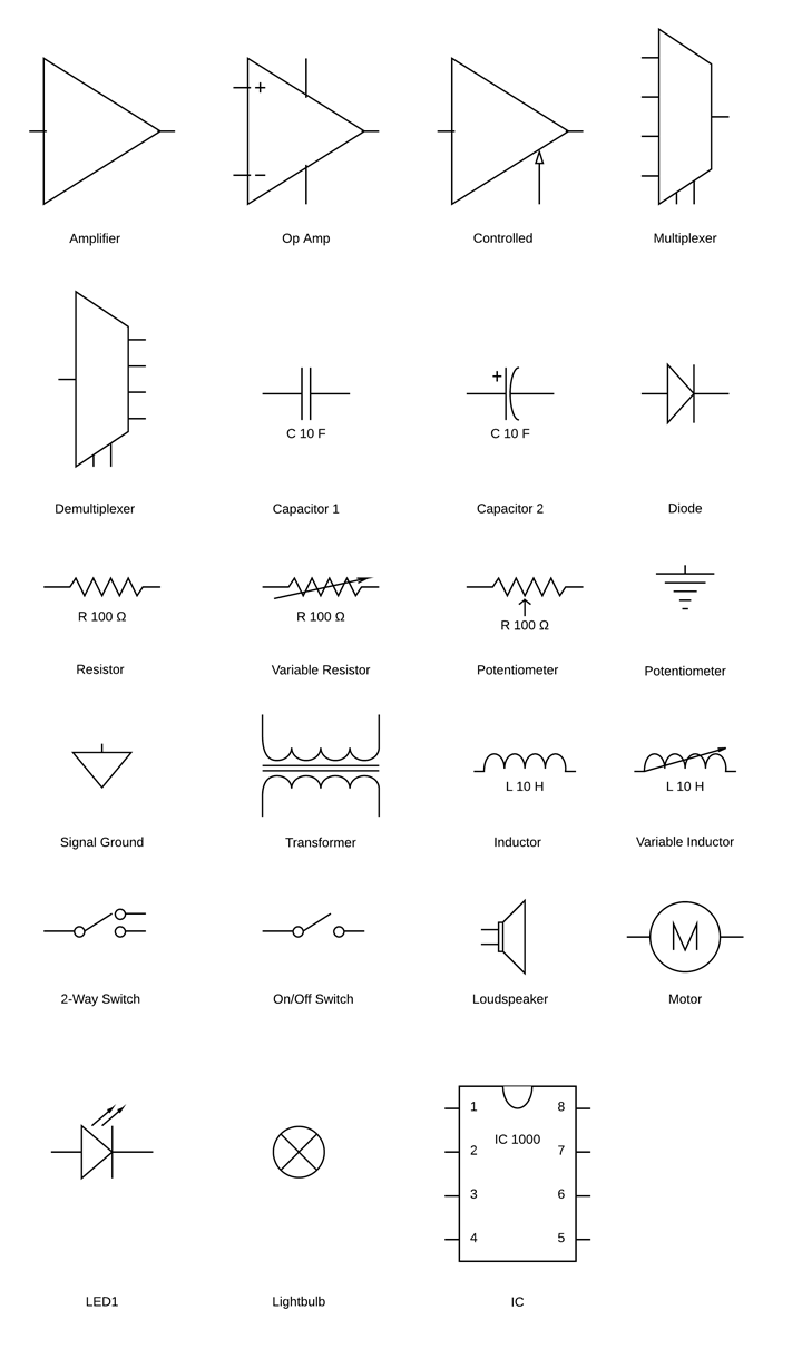
Electrical symbols are the most commonly used symbols in circuit diagramming. Amplifiers (denoted by triangle shapes) increase the output signal in your circuit. Capacitors (parallel lines) store energy in your system, while resistors (zigzag lines) reduce current flow. All electrical engineering students should become familiar with these three shapes, as they are universally used in circuit diagrams. In Lucidchart, simply hover over the shape to see its name. You can also search for a shape (e.g. light bulb) using our Iconfinder and Google image search results feature for more shape image options.

Power source circuit diagram symbols
Use power source symbols to indicate alternating and direct currents in a circuit diagram. Lucidchart has easy-to-use dialogs to let you switch the direction of the positive and negative charge icons, as well as the orientation and the voltage label. You can also make your circuit diagram stand out by adding a fill color with just one click.

Want to make a Circuit diagram of your own? Try Lucidchart. It's quick, easy, and completely free.
Make a circuit diagramTransistor circuit diagram symbols
Unlike a resistor symbol, a transistor symbol is used to indicate amplification or switches of power. There are three major transistor types: bipolar junction transistors (BJT), junction gate field-effect transistors (JFET), and metal oxide semiconductor field-effect transistors (MOSFET). Each type has its unique advantages and drawbacks. BJTs have high transconductance, whereas MOSFETs excel at low voltages. A useful mnemonic device for remembering which transistors are PNP (positive-negative-positive) and which are NPN (negative-positive-negative) is “not pointing in” for NPN and “pointing in proudly” for PNP.

Relay circuit diagram symbols
Relays form switches in your electrical circuit. In Lucidchart, there are four major types of relay symbols that are labeled. They include both the full name, e.g. Single Pole Single Throw, and its abbreviation—in this case, SPST. You can easily rotate a relay, or any other icon in Lucidchart, to fit the parameters of your circuit diagram.

Logic gate circuit diagram symbols
Logic gates perform logical functions (i.e. “and,” “not and,” or “exclusive or”) on one or more inputs to create a single output. Lucidchart has international-style logic gate icons, including an inverter. You can also choose from several types of flip-flops.

Voltmeters, charge symbols, waves and more
Our Miscellaneous library gives you even more options for customization. If you ever made a potato-powered battery for an elementary school science fair, you’re familiar with voltmeters. You can also drag and drop an ammeter, an inverter contact, and an electrical charge symbol onto your canvas.