Engineering diagrams: the difference between pictorial and schematic diagrams
Lucid Content
Reading time: about 6 min
Professionals and DIY enthusiasts rely on engineering diagrams to understand what components are included in a system, where these components are located, and how they connect and interact with each other. Understanding a visual representation of a system or a process flow is often easier than reading highly technical text describing the system or process.
Your level of expertise and what you are trying to accomplish will determine which type of diagram you will want to use. For example, a professional electrician may want to use a detailed schematic to track down and troubleshoot problems in an electrical system. On the other hand, if you are replacing a light switch in your kid’s bedroom, the simple pictorial diagram that accompanies the installation instructions is typically all you need to get the job done.
In this article, we will discuss the differences between schematic diagrams and pictorial diagrams to help you determine which type of diagram will be best for your project.
What is a pictorial diagram?
A pictorial diagram uses pictures to represent the different components of a particular system. Pictorial diagrams can vary in level of detail. Some diagrams may have realistic pictures to make the various components easier to identify. Others might have simple sketches that can easily be understood by the average person working on a weekend project.
Let's explore some pictorial diagrams that you may encounter.
Block diagram
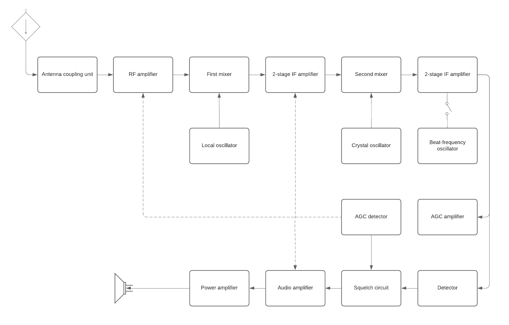
As the name implies, a block diagram uses simple block illustrations instead of standardized symbols or detailed images to represent the main components of a system. Block diagrams are often used in hardware and software design and in electrical engineering. They can also be used to create business data flow charts.
Block diagrams are typically less detailed than other types of diagrams and are meant to give you a high-level overview of a system’s components, the connections between each component, and the relationships between them. The simple labeled shapes make it easier for non-professionals to understand the basic concepts of a system.
These types of diagrams are used to troubleshoot problem areas in existing systems, make initial plans for a new system, and present new ideas.
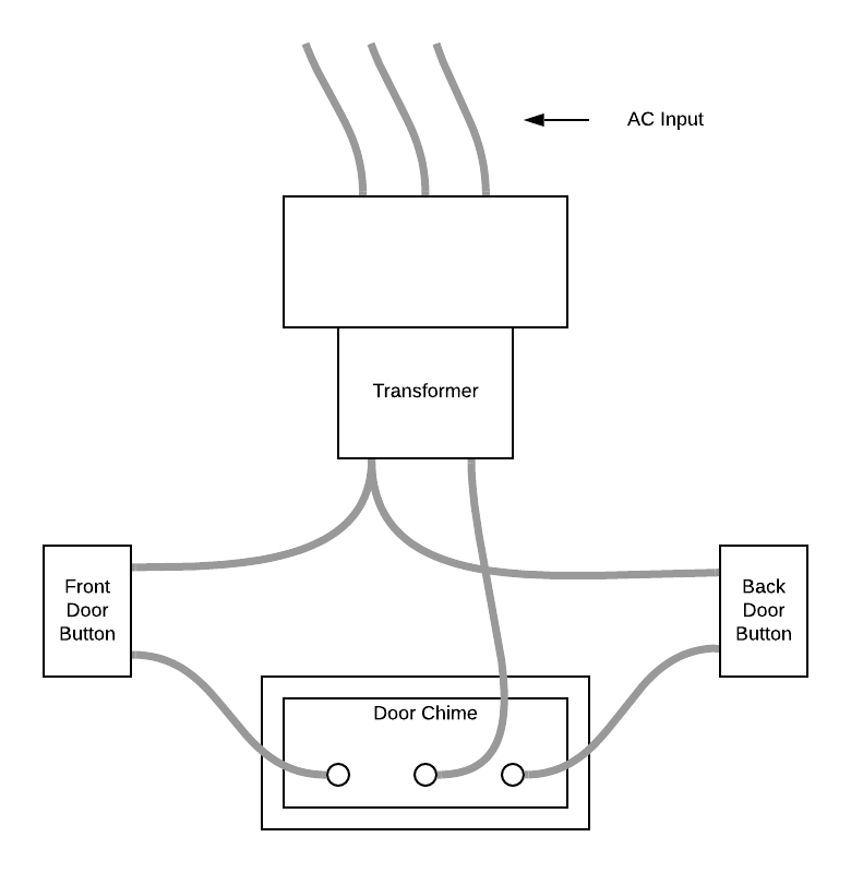
The following is an example of a block diagram showing the basic, high-level outline for wiring a doorbell chime with front door and back door push buttons. Notice that the diagram is not very detailed, but it gives you enough information to understand how to connect the doorbell buttons to the wires leading to the chime.

Get started on your own block diagram with this template.

Wiring diagram
This type of diagram is similar to a block diagram. Like a block diagram, a wiring diagram is a simplified graphical representation of an electrical circuit. The components of the system are displayed as simple shapes or diagrams. The main difference between a wiring diagram and a block diagram is that wiring diagrams are mainly used in electrical applications. These diagrams include information about power connections and simple information about the signal flow.
The wiring diagram example below gives you a little more information like wire colors and simple written steps to help you complete the circuit. This type of diagram is intended to be easily understood by the average homeowner and will typically be included with the instructions that accompany the hardware.

The following pictorial electric diagram is an example of a more detailed wiring for a front and back doorbell system. This type of drawing is still very simple, but includes enough detail that the average homeowner should be able to successfully install and wire a two doorbell system. A drawing like this one is likely to be included with the printed instructions that come with the doorbell hardware you purchase from your local home improvement store.

Even if you have never wired a doorbell before, the simple drawings help you to identify the various components and how they need to be connected to make the doorbell work properly. A pictorial diagram may not make you an expert electrical engineer, but it can help you complete simple do-it-yourself jobs.
What is a schematic diagram?
The word “schematic” means a plan, outline, or model. So a schematic diagram is a graphical representation of a plan or a model that is presented in a simple, accessible way. Schematics use simple lines and symbols to communicate information such as what, how, and where.
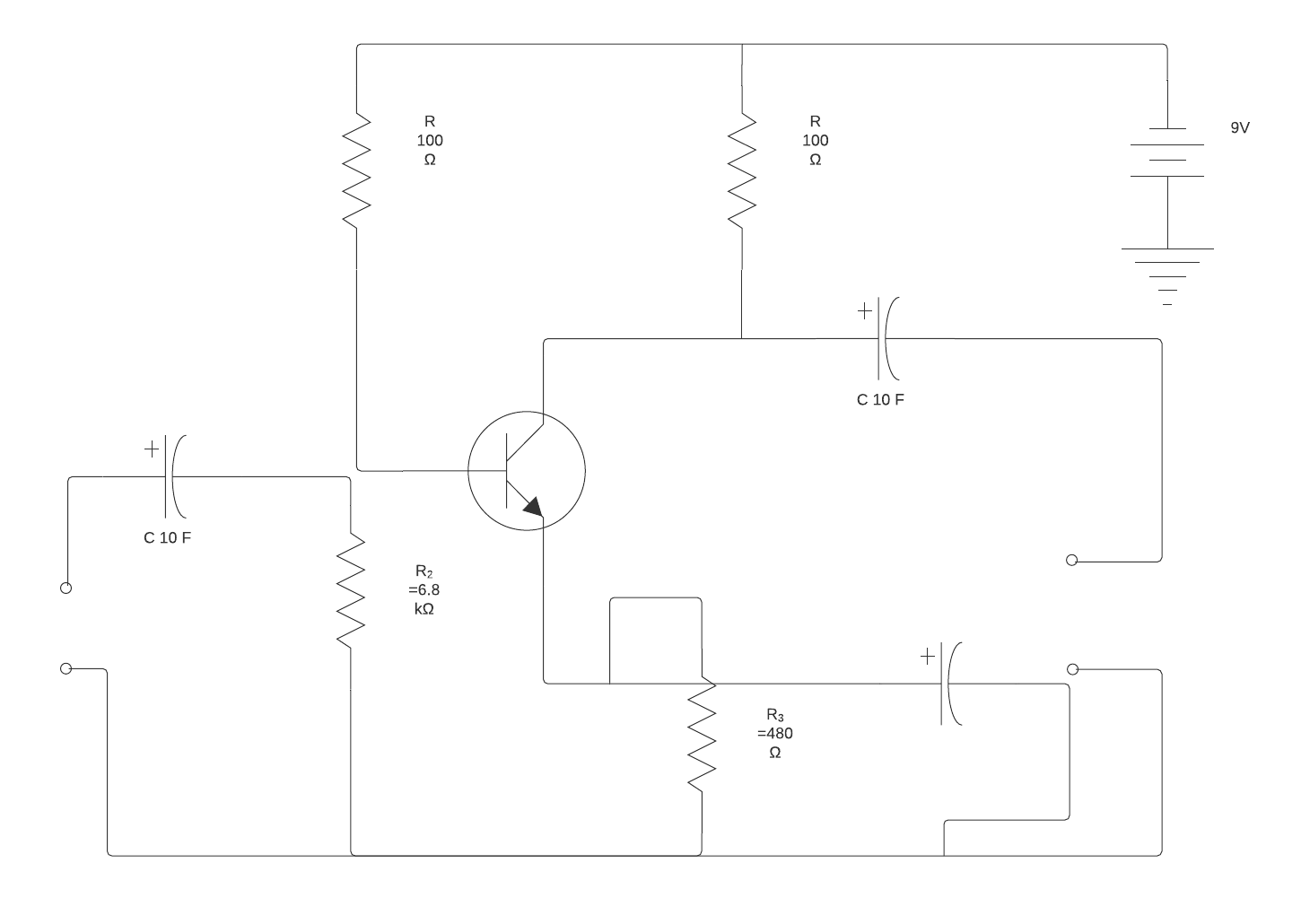
A schematic diagram used for electronics uses standardized symbols and simple line drawings to represent various electronic components. The standardized symbols make it possible for any experienced electrician to read and understand any schematic diagram. For example, a resistor is represented by a line with jagged teeth, which makes it easy to identify all the resistors in the schematic diagram below.

A professional electrician who has experience reading the type of schematic above should have no problem understanding what all of the symbols mean. But to an amateur, the schematic may simply look like a series of straight and squiggly lines.
Different types of schematic diagrams
Schematics are usually associated with engineering or electronics. However, any diagram that uses lines and symbols to communicate information can be considered a schematic. You probably encounter and interact with schematic diagrams in everyday life without ever needing to pull electrical wiring through walls.
For example, think of a simple bike trail map. It uses colored lines to represent the different trails and how they connect to each other. The white dots represent trailheads where riders can easily get on and off the trail, refill water bottles, and rest.
Schematic drawings are also used in manufacturing during the design stage. They help engineers understand how different parts fit together and interact to make the product work properly. In addition, a simple flowchart can be used as a schematic diagram that defines the manufacturing and distribution process.
Chemists use schematic drawings to describe how different elements interact with each other to create a product.
Pictorial diagrams, block diagrams, and wiring diagrams are the simplest diagrams and are best suited for the average homeowner or handyman tackling a weekend project. The diagrams include enough detail to identify components and to help you understand how to connect the components together. These simple diagrams are not meant for installing new systems or adding to existing systems. Rather, they are meant to be used with simple projects.
Schematic diagrams are more detailed and are meant to be used by professionals. The standardized symbols ensure that experienced workers can read and understand the system so they can troubleshoot problem areas, add new components to existing systems, and install new systems.

Create your own schematic diagram with this ready-to-use template.
Get startedAbout Lucidchart
Lucidchart, a cloud-based intelligent diagramming application, is a core component of Lucid Software's Visual Collaboration Suite. This intuitive, cloud-based solution empowers teams to collaborate in real-time to build flowcharts, mockups, UML diagrams, customer journey maps, and more. Lucidchart propels teams forward to build the future faster. Lucid is proud to serve top businesses around the world, including customers such as Google, GE, and NBC Universal, and 99% of the Fortune 500. Lucid partners with industry leaders, including Google, Atlassian, and Microsoft. Since its founding, Lucid has received numerous awards for its products, business, and workplace culture. For more information, visit lucidchart.com.
Related articles
7 tips for faster diagramming in Lucidchart
Whether you are a new diagrammer or a power user, check out these seven tips from Lucidchart product experts to learn how to diagram more efficiently.
