What is UML?
The Unified Modeling Language (UML) was created to forge a common, semantically and syntactically rich visual modeling language for the architecture, design, and implementation of complex software systems both structurally and behaviorally.
It is analogous to the blueprints used in other fields, and consists of different types of diagrams. In the aggregate, UML diagrams describe the boundary, structure, and the behavior of the system and the objects within it.
There are four problem-solving model categories: imperative, functional, declarative and object-oriented languages (OOP). In object-oriented languages, algorithms are expressed by defining ‘objects’ and having the objects interact with each other. Those objects are things to be manipulated and they exist in the real world. They can be buildings, widgets on a desktop, or human beings.
Object-oriented languages dominate the programming world because they model real-world objects. UML is a combination of several object-oriented notations: Object-Oriented Design, Object Modeling Technique, and Object-Oriented Software Engineering.
UML uses the strengths of these three approaches to present a more consistent methodology that's easier to use. UML represents best practices for building and documenting different aspects of software and business system modeling.
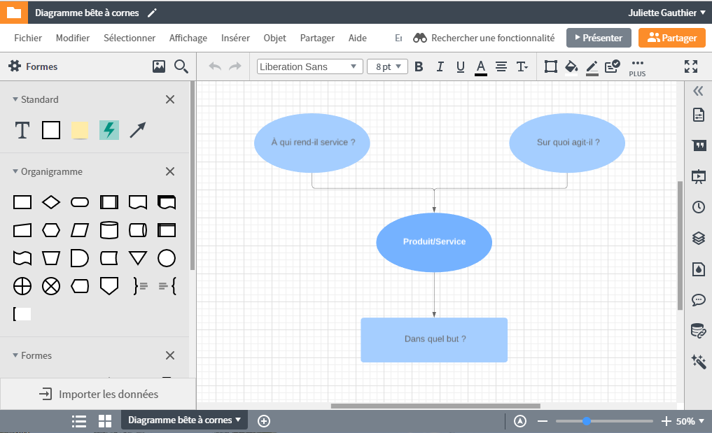
Create a UML diagram in Lucidchart
- Create your first UML diagram from template, a blank canvas or import a document.
- Create professional UML diagrams to visualize complex systems.
- Save time with our UML sequence markup tool.
- Use Lucidchart’s UML shape library to access industry-standard UML shapes.
- Share your UML diagram with your team and start collaborating on it
The history and origins of UML
‘The Three Amigos’ of software engineering as they were known, had evolved other methodologies. They teamed up to provide clarity for programmers by creating new standards. The collaboration between Grady, Booch, and Rumbaugh made all three methods stronger and improved the final product.
The efforts of these thinkers resulted in the release of the UML 0.9 and 0.91 documents in 1996. It soon became clear that several organizations, including Microsoft, Oracle, and IBM saw UML as critical to their own business development. They, along with many other individuals and companies, established resources that could develop a full-fledged modeling language. The Three Amigos published The Unified Modeling Language User Guide in 1999, and an update which includes information about UML 2.0 in the 2005 Second Edition.
OMG: It has a different meaning
According to their website, The Object Management Group® (OMG®) is an international, open membership, not-for-profit technology standards consortium, founded in 1989. OMG standards are driven by vendors, end-users, academic institutions and government agencies. OMG Task Forces develop enterprise integration standards for a wide range of technologies and an even wider range of industries. OMG’s modeling standards, including the UML and Model Driven Architecture® (MDA®), enable powerful visual design, execution and maintenance of software and other processes.
OMG oversees the definition and maintenance of UML specifications. This oversight gives engineers and programmers the ability to use one language for many purposes during all phases of the software lifecycle for all system sizes.
The OMG defines the purpose of the UML as:
- Providing system architects, software engineers, and software developers with tools for analysis, design, and implementation of software-based systems as well as for modeling business and similar processes.
- Advancing the state of the industry by enabling object visual modeling tool interoperability. However, to enable meaningful exchange of model information between tools, agreement on semantics and notation is required.
UML meets the following requirements:
- Setting a formal definition of a common Meta-Object Facility (MOF)-based meta-model that specifies the abstract syntax of the UML. The abstract syntax defines the set of UML modeling concepts, their attributes and their relationships, as well as the rules for combining these concepts to construct partial or complete UML models.
- Providing a detailed explanation of the semantics of each UML modeling concept. The semantics define, in a technology independent manner, how the UML concepts are to be realized by computers.
- Specifying the human-readable notation elements for representing the individual UML modeling concepts as well as rules for combining them into a variety of different diagram types corresponding to different aspects of modeled systems.
- Defining ways in which UML tools can be made compliant with this specification. This is supported (in a separate specification) with an XML-based specification of corresponding model interchange formats (XMI) that must be realized by compliant tools.
Types of UML diagrams
UML uses elements and associates them in different ways to form diagrams that represent static, or structural aspects of a system, and behavioral diagrams, which capture the dynamic aspects of a system.
Structural UML diagrams
- Class Diagram The most commonly used UML diagram, and the principal foundation of any object-oriented solution. Classes within a system, attributes and operations and the relationship between each class. Classes are grouped together to create class diagrams when diagramming large systems.
- Component Diagram Displays the structural relationship of software system elements, most often employed when working with complex systems with multiple components. Components communicate using interfaces.
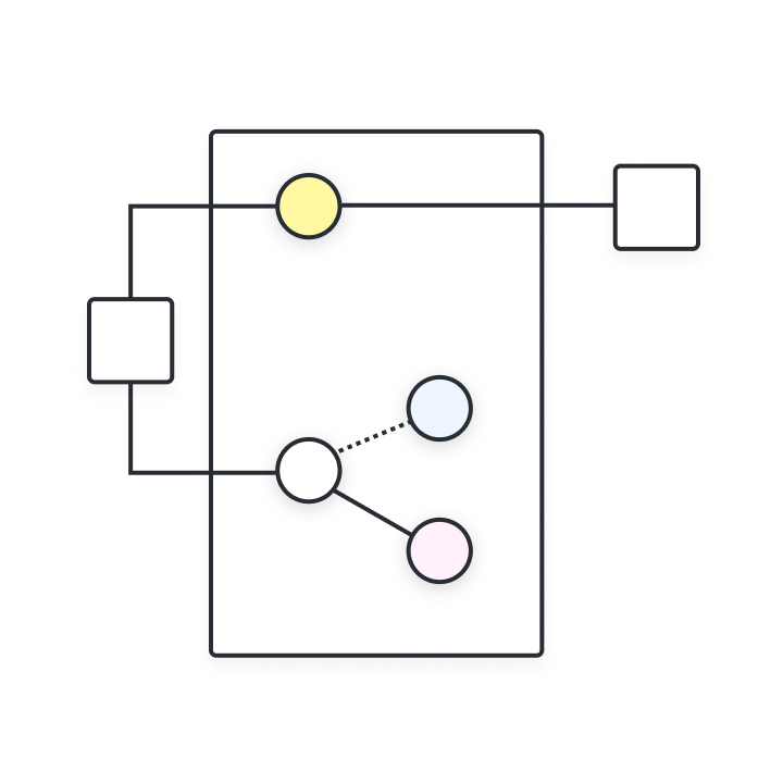
- Composite Structure Diagram Composite structure diagrams are used to show the internal structure of a class.
- Deployment Diagram Illustrates system hardware and its software. Useful when a software solution is deployed across multiple machines with unique configurations.
- Object Diagram Shows the relationship between objects using real world examples and illustrates how a system will look at any given time. Because data is available within objects, they can be used to clarify relationships between objects.
- Package Diagram There are two special types of dependencies defined between packages: package import and package merge. Packages can represent the different levels of a system to reveal the architecture. Package dependencies can be marked to show the communication mechanism between levels.
Behavioral UML diagrams
- Activity Diagrams Graphically represented business or operational workflows to show the activity of any part or component in the system. Activity diagrams are used as an alternative to State Machine diagrams.
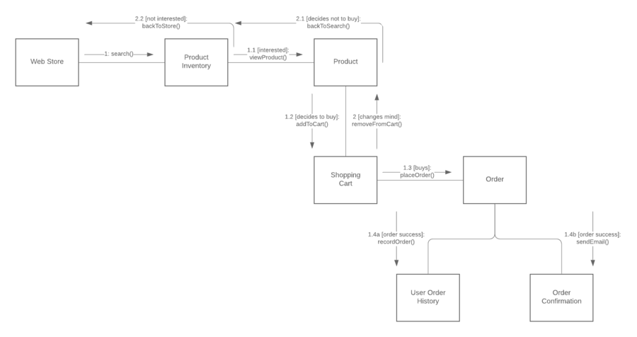
- Communication Diagram Similar to sequence diagrams, but the focus is on messages passed between objects. The same information can be represented using a sequence diagram and different objects.
- Interaction Overview Diagram There are seven types of interaction diagrams, and this diagram shows the sequence in which they act.
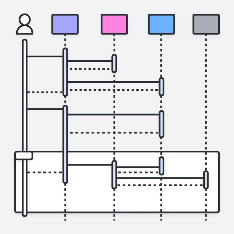
- Sequence Diagram Shows how objects interact with each other and the order of occurrence. They represent interactions for a particular scenario.
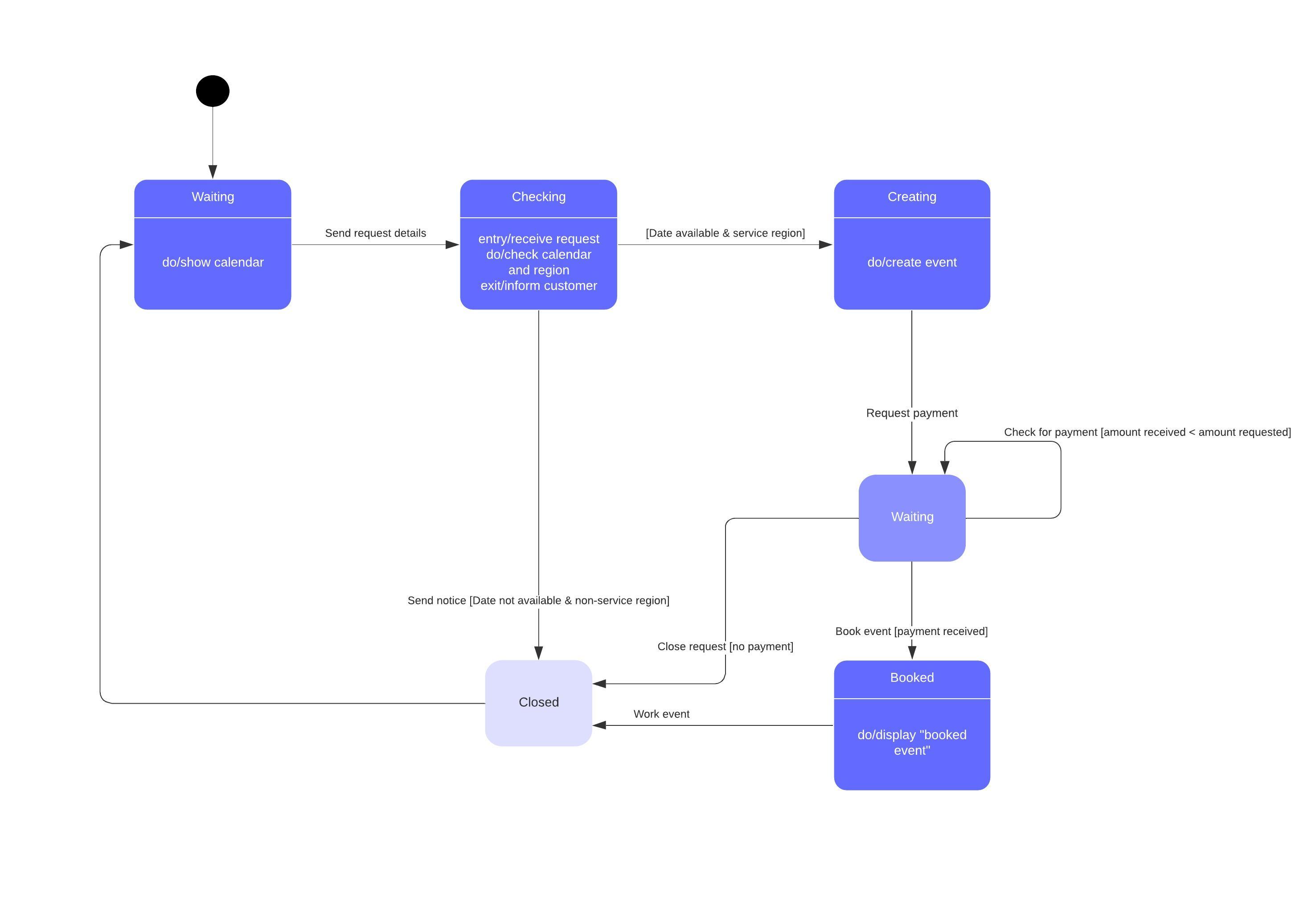
- State Diagram Similar to activity diagrams, they describe the behavior of objects that behave in varying ways in their current state.
- Timing Diagram Like Sequence Diagrams, the behavior of objects in a given time frame are represented. If there is a single object, the diagram is simple. With more than one object, interactions of objects are shown during that particular time frame.
- Use Case Diagram Represents a particular functionality of a system, created to illustrate how functionalities relate and their internal/external controllers (actors).
UML terms glossary
Familiarize yourself with the UML vocabulary, with this list culled from the UML 2.4.1 document intended to help OMG non-members understand commonly used terms.
- Abstract syntax compliance Users can move models across different tools, even if they use different notations
- Common Warehouse Metamodel (CWM) Standard interfaces that are used to enable interchange of warehouse and business intelligence metadata between warehouse tools, warehouse platforms and warehouse metadata repositories in distributed heterogeneous environments
- Concrete syntax compliance Users can continue to use a notation they are familiar with across different tools
- Core In the context of UML, the core usually refers to the "Core package" which is a complete metamodel particularly designed for high reusability
- Language Unit Consists of a collection of tightly coupled modeling concepts that provide users with the power to represent aspects of the system under study according to a particular paradigm or formalism
- Level 0 (L0) Bottom compliance level for UML infrastructure - a single language unit that provides for modeling the kinds of class-based structures encountered in most popular object-oriented programming languages
- Meta Object Facility (MOF) An OMG modeling specification that provides the basis for metamodel definitions in OMG's family of MDA languages
- Metamodel Defines the language and processes from which to form a model
- Metamodel Constructs (LM) Second compliance level in the UML infrastructure - an extra language unit for more advanced class-based structures used for building metamodels (using CMOF) such as UML itself. UML only has two compliance levels
- Model Driven Architecture (MDA) An approach and a plan to achieve a cohesive set of model-driven technology specifications
- Object Constraint Language (OCL) A declarative language for describing rules that apply to Unified Modeling Language. OCL supplements UML by providing terms and flowchart symbols that are more precise than natural language but less difficult to master than mathematics
- Object Management Group (OMG) Is a not-for-profit computer industry specifications consortium whose members define and maintain the UML specification
- UML 1 First version of the Unified Modeling Language
- Unified Modeling Language (UML) A visual language for specifying, constructing, and documenting the artifacts of systems
- XMI An XML-based specification of corresponding model interchange formats
View the complete MOF document
Download the complete UML 2.4.1 Infrastructure document.
Modeling concepts specified by UML
System development focuses on three overall different system models:
- Functional: These are Use Case diagrams, which describe system functionality from the point of view of the user.
- Object: These are Class Diagrams, which describe the structure of the system in terms of objects, attributes, associations, and operations.
- Dynamic: Interaction Diagrams, State Machine Diagrams, and Activity Diagrams are used to describe the internal behavior of the system.
These system models are visualized through two different types of diagrams: structural and behavioral.
Object-oriented concepts in UML
The objects in UML are real world entities that exist around us. In software development, objects can be used to describe, or model, the system being created in terms that are relevant to the domain. Objects also allow the decomposition of complex systems into understandable components that allow one piece to be built at a time.
Here are some fundamental concepts of an object-oriented world:
- Objects Represent an entity and the basic building block.
- Class Blue print of an object.
- Abstraction Behavior of a real world entity.
- Encapsulation Mechanism of binding the data together and hiding them from outside world.
- Inheritance Mechanism of making new classes from existing one.
- Polymorphism It defines the mechanism to exists in different forms.
Lucidchart makes it easy to draw UML diagrams
You can start UML diagramming now with Lucidchart. We make it simple, efficient, and even fun.
- Simple to use If you’re making a UML diagram, you clearly know what you’re doing, but we want to make it as easy as possible to get the job done. You’ll save time with Lucidchart’s polished interface and smart drag-and-drop editor.
- Extensive shape library Draw state diagrams, activity diagrams, use case diagrams, and more. With an extensive shape and connector library, you'll find everything you need.
- Fully integrated Lucidchart is fully integrated with G Suite. Once you get started with Lucidchart, you’ll be able to find us right in your Google productivity suite along with Gmail and Google Drive. Plus, you can use the same login you use for Google.
- Enables collaboration You can easily share your UML diagram with your co-workers, clients, or your boss. Your diagrams can be embedded into a webpage or published as a PDF, and Lucidchart’s presentation mode turns your creation into a great-looking visual aid.
- Visio import/export It’s easy to import and export Visio files so you can save the work you've already done. The whole experience is fast and seamless.